





Skip to content

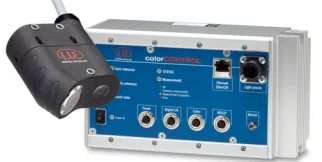
Configure: colorCONTROL ACS

Choose what goes with the sensor. Required items are pre-selected; the list is checked before it goes to your quote.

Base product

colorCONTROL ACS eli-s-af2db210e8653bb69845c6c0 Required

Sensor measuring rate
2 kHz
Maximum rate with a compatible controller
2 kHz
Communication
Ethernet
Signal type
Not specified
What the system must do

Leave a field empty if it does not matter. Only components that form one complete system meeting every requirement stay available.

Communication
Signal type
Step 1 — Controllers
  • Measuring rate
    Not specified
    Communication
    Not specified
    Inputs
    Not specified
    Signal type
    Not specified
    Exact source configuration configuration-f1ba85a882a0031d82c69681; no substitution of interface variant or simultaneous performance inferred.
Step 2 — Cables
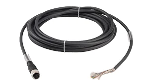
  • Only for source configuration configuration-1ff0162d7b3eaa5be1f5647f: ACS7000 + ACS1-30/0; selected configuration must be matched before display.; ACS-specific port and pinout; not a CFO electrical or CFS optical lead. RS422 maximum 5 m; power/color-output maximum 10 m. The 5 m digital-I/O article differs between drawing and table: confirm current order code.
  • Only for source configuration configuration-1ff0162d7b3eaa5be1f5647f: ACS7000 + ACS1-30/0; selected configuration must be matched before display.; ACS-specific port and pinout; not a CFO electrical or CFS optical lead. RS422 maximum 5 m; power/color-output maximum 10 m. The 5 m digital-I/O article differs between drawing and table: confirm current order code.
  • Only for source configuration configuration-1ff0162d7b3eaa5be1f5647f: ACS7000 + ACS1-30/0; selected configuration must be matched before display.; ACS-specific port and pinout; not a CFO electrical or CFS optical lead. RS422 maximum 5 m; power/color-output maximum 10 m. The 5 m digital-I/O article differs between drawing and table: confirm current order code.
  • Only for source configuration configuration-1ff0162d7b3eaa5be1f5647f: ACS7000 + ACS1-30/0; selected configuration must be matched before display.; ACS-specific port and pinout; not a CFO electrical or CFS optical lead. RS422 maximum 5 m; power/color-output maximum 10 m. The 5 m digital-I/O article differs between drawing and table: confirm current order code.
  • Only for source configuration configuration-1ff0162d7b3eaa5be1f5647f: ACS7000 + ACS1-30/0; selected configuration must be matched before display.; ACS-specific port and pinout; not a CFO electrical or CFS optical lead. RS422 maximum 5 m; power/color-output maximum 10 m. The 5 m digital-I/O article differs between drawing and table: confirm current order code.
  • Only for source configuration configuration-1ff0162d7b3eaa5be1f5647f: ACS7000 + ACS1-30/0; selected configuration must be matched before display.; ACS-specific port and pinout; not a CFO electrical or CFS optical lead. RS422 maximum 5 m; power/color-output maximum 10 m. The 5 m digital-I/O article differs between drawing and table: confirm current order code.
  • Only for source configuration configuration-1ff0162d7b3eaa5be1f5647f: ACS7000 + ACS1-30/0; selected configuration must be matched before display.; ACS-specific port and pinout; not a CFO electrical or CFS optical lead. RS422 maximum 5 m; power/color-output maximum 10 m. The 5 m digital-I/O article differs between drawing and table: confirm current order code.
  • Only for source configuration configuration-1ff0162d7b3eaa5be1f5647f: ACS7000 + ACS1-30/0; selected configuration must be matched before display.; ACS-specific port and pinout; not a CFO electrical or CFS optical lead. RS422 maximum 5 m; power/color-output maximum 10 m. The 5 m digital-I/O article differs between drawing and table: confirm current order code.
  • Only for source configuration configuration-1ff0162d7b3eaa5be1f5647f: ACS7000 + ACS1-30/0; selected configuration must be matched before display.; ACS-specific port and pinout; not a CFO electrical or CFS optical lead. RS422 maximum 5 m; power/color-output maximum 10 m. The 5 m digital-I/O article differs between drawing and table: confirm current order code.
  • Only for source configuration configuration-1ff0162d7b3eaa5be1f5647f: ACS7000 + ACS1-30/0; selected configuration must be matched before display.; ACS-specific port and pinout; not a CFO electrical or CFS optical lead. RS422 maximum 5 m; power/color-output maximum 10 m. The 5 m digital-I/O article differs between drawing and table: confirm current order code.
  • Only for source configuration configuration-1ff0162d7b3eaa5be1f5647f: ACS7000 + ACS1-30/0; selected configuration must be matched before display.; ACS-specific port and pinout; not a CFO electrical or CFS optical lead. RS422 maximum 5 m; power/color-output maximum 10 m. The 5 m digital-I/O article differs between drawing and table: confirm current order code.
  • Only for source configuration configuration-1ff0162d7b3eaa5be1f5647f: ACS7000 + ACS1-30/0; selected configuration must be matched before display.; ACS-specific port and pinout; not a CFO electrical or CFS optical lead. RS422 maximum 5 m; power/color-output maximum 10 m. The 5 m digital-I/O article differs between drawing and table: confirm current order code.
Step 3 — Power supplies
  • Only for source configuration configuration-1ff0162d7b3eaa5be1f5647f: ACS7000 + ACS1-30/0; selected configuration must be matched before display.
Step 4 — Mounting
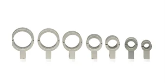
  • Only for source configuration configuration-1ff0162d7b3eaa5be1f5647f: ACS7000 + ACS1-30/0; selected configuration must be matched before display.; Match the exact ACS head and plate drawing, illumination geometry and any distance-compensation sensor; not a CFS/CFO adapter.
  • Only for source configuration configuration-1ff0162d7b3eaa5be1f5647f: ACS7000 + ACS1-30/0; selected configuration must be matched before display.; Match the exact ACS head and plate drawing, illumination geometry and any distance-compensation sensor; not a CFS/CFO adapter.
  • Only for source configuration configuration-1ff0162d7b3eaa5be1f5647f: ACS7000 + ACS1-30/0; selected configuration must be matched before display.; Match the exact ACS head and plate drawing, illumination geometry and any distance-compensation sensor; not a CFS/CFO adapter.
  • Only for source configuration configuration-1ff0162d7b3eaa5be1f5647f: ACS7000 + ACS1-30/0; selected configuration must be matched before display.; Match the exact ACS head and plate drawing, illumination geometry and any distance-compensation sensor; not a CFS/CFO adapter.
  • Only for source configuration configuration-1ff0162d7b3eaa5be1f5647f: ACS7000 + ACS1-30/0; selected configuration must be matched before display.; Match the exact ACS head and plate drawing, illumination geometry and any distance-compensation sensor; not a CFS/CFO adapter.
  • Only for source configuration configuration-1ff0162d7b3eaa5be1f5647f: ACS7000 + ACS1-30/0; selected configuration must be matched before display.; Match the exact ACS head and plate drawing, illumination geometry and any distance-compensation sensor; not a CFS/CFO adapter.
  • Only for source configuration configuration-1ff0162d7b3eaa5be1f5647f: ACS7000 + ACS1-30/0; selected configuration must be matched before display.; Match the exact ACS head and plate drawing, illumination geometry and any distance-compensation sensor; not a CFS/CFO adapter.
  • Only for source configuration configuration-1ff0162d7b3eaa5be1f5647f: ACS7000 + ACS1-30/0; selected configuration must be matched before display.; Match the exact ACS head and plate drawing, illumination geometry and any distance-compensation sensor; not a CFS/CFO adapter.
  • Only for source configuration configuration-1ff0162d7b3eaa5be1f5647f: ACS7000 + ACS1-30/0; selected configuration must be matched before display.; Match the exact ACS head and plate drawing, illumination geometry and any distance-compensation sensor; not a CFS/CFO adapter.
Step 5 — Accessories
  • Only for source configuration configuration-1ff0162d7b3eaa5be1f5647f: ACS7000 + ACS1-30/0; selected configuration must be matched before display.; Select calibrated versus uncalibrated reference and the correct calibration method; certificate does not change the head's published repeatability.
  • Only for source configuration configuration-1ff0162d7b3eaa5be1f5647f: ACS7000 + ACS1-30/0; selected configuration must be matched before display.; Select calibrated versus uncalibrated reference and the correct calibration method; certificate does not change the head's published repeatability.
  • Only for source configuration configuration-1ff0162d7b3eaa5be1f5647f: ACS7000 + ACS1-30/0; selected configuration must be matched before display.; Select calibrated versus uncalibrated reference and the correct calibration method; certificate does not change the head's published repeatability.
  • Only for source configuration configuration-1ff0162d7b3eaa5be1f5647f: ACS7000 + ACS1-30/0; selected configuration must be matched before display.; Select calibrated versus uncalibrated reference and the correct calibration method; certificate does not change the head's published repeatability.

Required components are part of every system and cannot be removed.

Components marked one per channel follow the number of measurement channels you enter.

Your system