














Rotor stress tests in the test bench
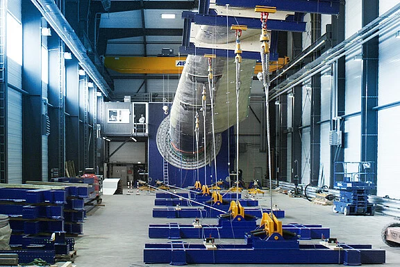
Test rigs have been developed for load tests on wind turbine rotor blades and simulate the real loads caused by high winds and weather. The tip of the rotor blade can be distorted by up to 10m due to mechanical loads. Draw-wire sensors are used on the test rig for measuring the distortion. Two sensors per traction point measure the deflection and torsion of the rotor blade. The draw-wire sensors operate with measuring ranges between 3 m and 10 m. The digital signal output is provided for further simulations. Test rigs have been developed for load tests on wind turbine rotor blades and simulate the real loads caused by high winds and weather. The tip of the rotor blade can be distorted by up to 10m due to mechanical loads. Draw-wire sensors are used on the test rig for measuring the distortion. Two sensors per traction point measure the deflection and torsion of the rotor blade. The draw-wire sensors operate with measuring ranges between 3 m and 10 m. The digital signal output is provided for further simulations.
Test rigs have been developed for load tests on wind turbine rotor blades and simulate the real loads caused by high winds and weather. The tip of the rotor blade can be distorted by up to 10m due to mechanical loads. Draw-wire sensors are used on the test rig for measuring the distortion. Two sensors per traction point measure the deflection and torsion of the rotor blade. The draw-wire sensors operate with measuring ranges between 3 m and 10 m. The digital signal output is provided for further simulations. Test rigs have been developed for load tests on wind turbine rotor blades and simulate the real loads caused by high winds and weather. The tip of the rotor blade can be distorted by up to 10m due to mechanical loads. Draw-wire sensors are used on the test rig for measuring the distortion. Two sensors per traction point measure the deflection and torsion of the rotor blade. The draw-wire sensors operate with measuring ranges between 3 m and 10 m. The digital signal output is provided for further simulations.
Application challenge
Test rigs have been developed for load tests on wind turbine rotor blades and simulate the real loads caused by high winds and weather. The tip of the rotor blade can be distorted by up to 10m due to mechanical loads. Draw-wire sensors are used on the test rig for measuring the distortion. Two sensors per traction point measure the deflection and torsion of the rotor blade. The draw-wire sensors operate with measuring ranges between 3 m and 10 m. The digital signal output is provided for further simulations.
Measurement method and system
Test rigs have been developed for load tests on wind turbine rotor blades and simulate the real loads caused by high winds and weather. The tip of the rotor blade can be distorted by up to 10m due to mechanical loads. Draw-wire sensors are used on the test rig for measuring the distortion. Two sensors per traction point measure the deflection and torsion of the rotor blade. The draw-wire sensors operate with measuring ranges between 3 m and 10 m. The digital signal output is provided for further simulations.
The problem
Test rigs have been developed for load tests on wind turbine rotor blades and simulate the real loads caused by high winds and weather. The tip of the rotor blade can be distorted by up to 10m due to mechanical loads. Draw-wire sensors are used on the test rig for measuring the distortion. Two sensors per traction point measure the deflection and torsion of the rotor blade. The draw-wire sensors operate with measuring ranges between 3 m and 10 m. The digital signal output is provided for further simulations.
The method
Test rigs have been developed for load tests on wind turbine rotor blades and simulate the real loads caused by high winds and weather. The tip of the rotor blade can be distorted by up to 10m due to mechanical loads. Draw-wire sensors are used on the test rig for measuring the distortion. Two sensors per traction point measure the deflection and torsion of the rotor blade. The draw-wire sensors operate with measuring ranges between 3 m and 10 m. The digital signal output is provided for further simulations.