
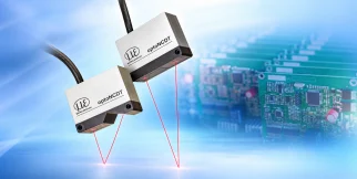
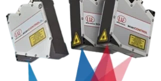
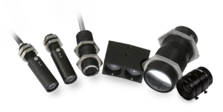
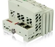









scanCONTROL 2510
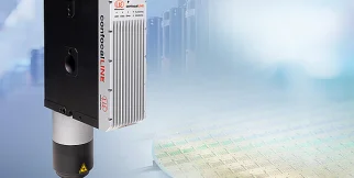
scanCONTROL 2510: sensors and measurement devices by Micro-Epsilon for measurement & 3d systems.
Download the datasheet (opens in a new tab) This series on the Micro-Epsilon site (opens in a new tab)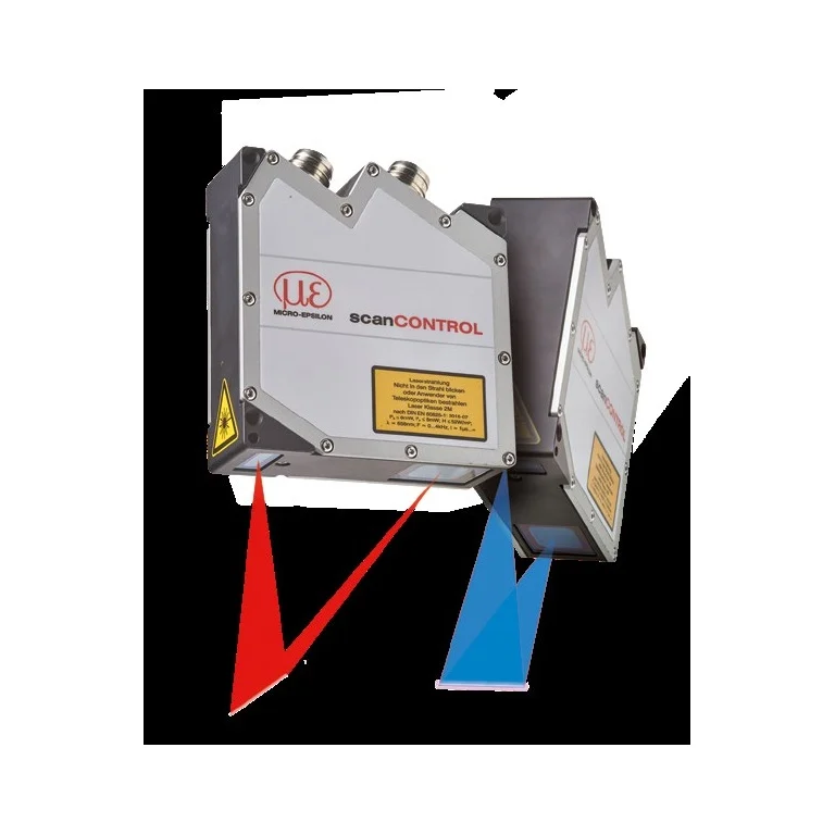
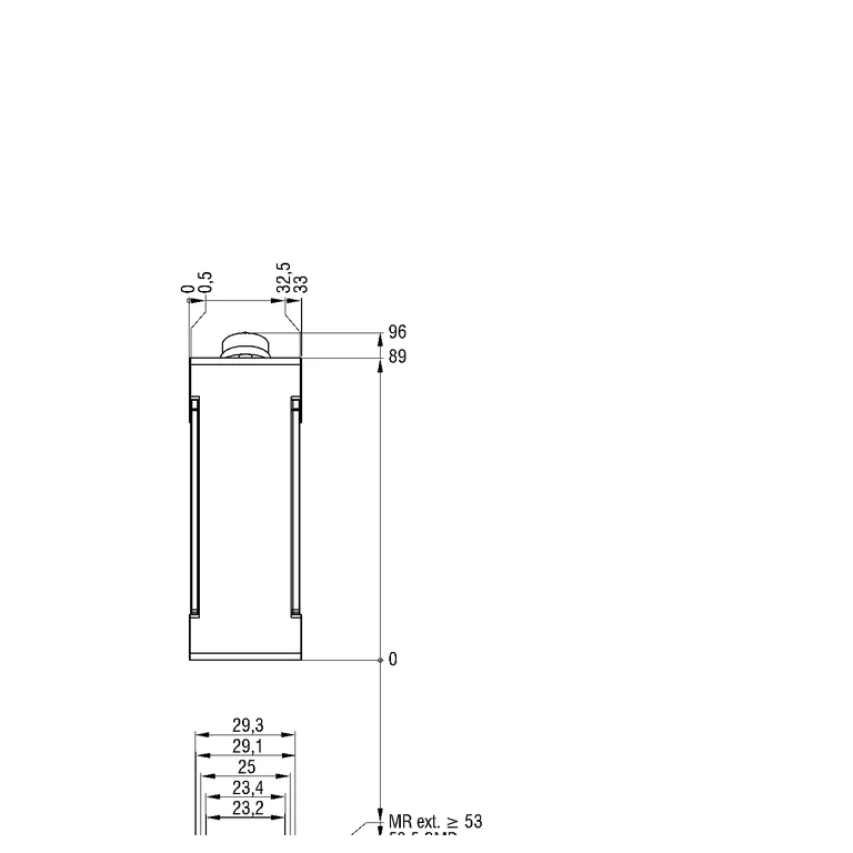
Shared technical specifications for the series
Properties every model in the series has. What differs is in the models table below.
Range across models
The span covered by the models of the series together — not the range of each model.
| Z measuring range | 26–265 mm |
|---|---|
| Accuracy | 2–12 µm |
| Working distance | 53–260 mm |
| X resolution | 45.78125–224.21875 µm |
| X measuring range | 29.3–143.5 mm |
Models in the series
One column per model: what differs between the models of the series.
| Parameter | scanCONTROL 2510-100 eli-m-41046c9ece8f8c9d0af8b1db | scanCONTROL 2510-25 eli-m-46cc940dc822542a2b77d446 | scanCONTROL 2510-50 eli-m-d0cf74ded3a3ecf4d710f813 |
|---|---|---|---|
| Z measuring range | 265 mm | 26 mm | 60 mm |
| Operating temperature | 0–45 °C | 0–45 °C | 0–45 °C |
| Interfaces | ethernet | ethernet | ethernet |
| Accuracy | 12 µm | 2 µm | 4 µm |
| ADC sampling rate | 2000 samples/s | 2000 samples/s | 2000 samples/s |
| Y measuring range | 0 mm | 0 mm | 0 mm |
| Working distance | 80–260 mm | 53–79 mm | 65–125 mm |
| Protection class (DIN EN 60529) | ip65 | ip65 | ip65 |
| X resolution | 224.21875 µm | 45.78125 µm | 93.75 µm |
| interface_specification | Digital I/O | Digital I/O | Digital I/O |
| Points per profile | 640 points/profile | 640 points/profile | 640 points/profile |
| quantity_specification | X field up to 143.5 mm and Z range up to 265 mm; Y is generated by encoder-synchronized travel. | X field up to 29.3 mm and Z range up to 26 mm; Y is generated by encoder-synchronized travel. | X field up to 60 mm and Z range up to 60 mm; Y is generated by encoder-synchronized travel. |
| X measuring range | 143.5 mm | 29.3 mm | 60 mm |
| source_three_d_scanner_type | Laser line | Laser line | Laser line |
| source_sampling_rate_basis | scanCONTROL 2510-100 catalog maximum profile frequency | scanCONTROL 2510-25 catalog maximum profile frequency | scanCONTROL 2510-50 catalog maximum profile frequency |
| Status | Active | Active | Active |
| Datasheet | PDF — scanCONTROL 2510-100 (opens in a new tab) | PDF — scanCONTROL 2510-25 (opens in a new tab) | PDF — scanCONTROL 2510-50 (opens in a new tab) |
The industries we serve
-
-
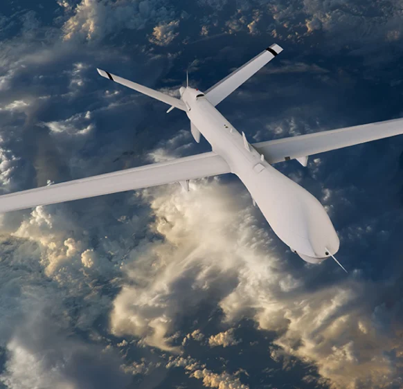
Aerospace
- Aircraft door-lock position detection
- Airlines & Aerospace Our balancing machines and moment weighing scales for aerospace drives ensure maximum precision, ease of use, and modular flexibility delivering reliability and performance without compromise contributing to your economic success.
- Automatic balancing machines Automatic balancing machines from Schenck are advanced solutions for precise balancing of rotating components in automated production processes. We offer systems and stations for balancing crankshafts, wheels and tires, turbochargers, electric armatures, drives, axle drive units, torque converters, drive shafts, disc-shaped rotors, as well as fans. Our systems increase productivity, ensure consistent quality, and are tailored to the needs of the automotive, energy, and industrial sectors.
-
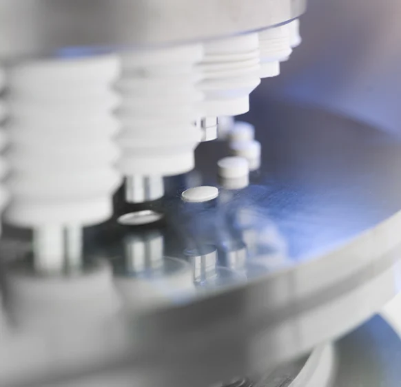
Medical industry
-
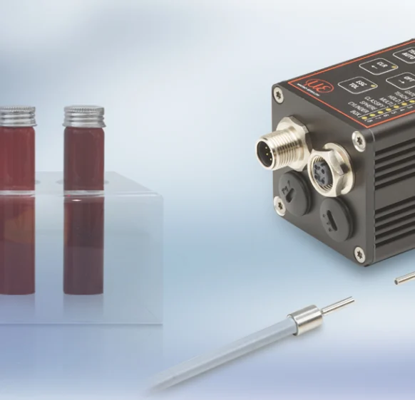
Environment
-
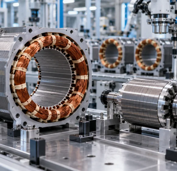
Electric motor manufacturing
-
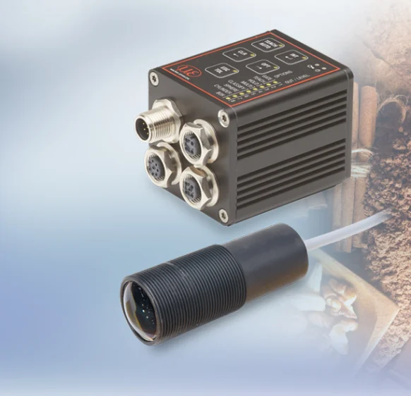
Food industry
-
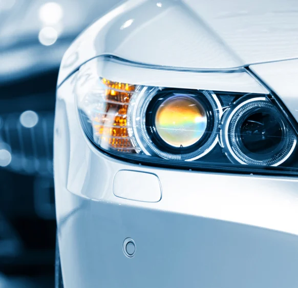
Automotive industry
- Airlines & Aerospace Our balancing machines and moment weighing scales for aerospace drives ensure maximum precision, ease of use, and modular flexibility delivering reliability and performance without compromise contributing to your economic success.
- Automatic balancing machines Automatic balancing machines from Schenck are advanced solutions for precise balancing of rotating components in automated production processes. We offer systems and stations for balancing crankshafts, wheels and tires, turbochargers, electric armatures, drives, axle drive units, torque converters, drive shafts, disc-shaped rotors, as well as fans. Our systems increase productivity, ensure consistent quality, and are tailored to the needs of the automotive, energy, and industrial sectors.
- Axle Drives With our balancing machines for front and rear axle transmissions, the measured unbalance is corrected by drilling into the drive flanges of the transmissions (welding optional). We support you with our interdisciplinary expertise in the production of front and rear axle transmissions from the initial idea to the design stage through to series production.
-
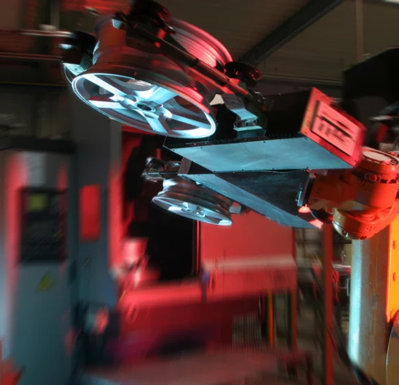
Industrial automation
-
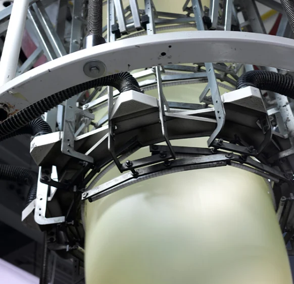
Plastics
-
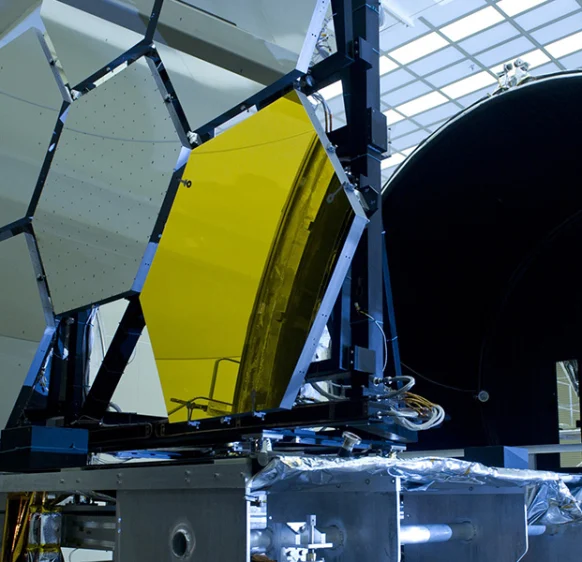
Optics
-
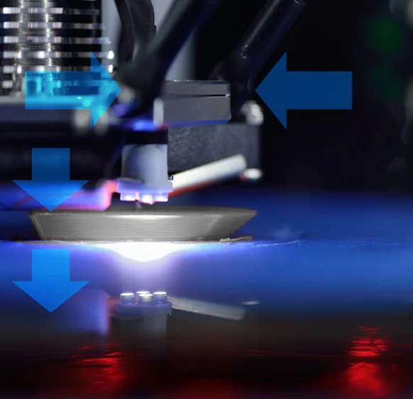
3D printing
-
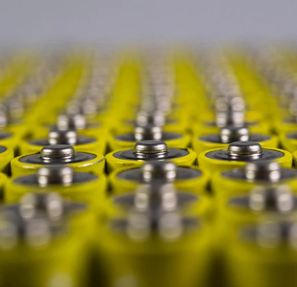
Battery manufacturing
Frequently asked questions
Answers to the most common questions about our products and services
SMART programs are configured in Configuration Tools and stored in the head. After setup the head outputs selected measurement values.
Evaluation includes angles, steps, gaps and distances in the profile. Define the region and appropriate measurement program.
Use an Output Unit with a suitable analog terminal from the accessory list. This is an additional system configuration, not an onboard head output.
No. Gateway measurement-value transfer depends on sensor count and communication path. Check it separately from profile acquisition rate.
The table conditions the rating on connected interfaces. Cable, adapter and Output Unit also need their own environmental checks.
Get a quote or advice
Tell us what you need and an engineer will come back to you.
Request a quote for this product