
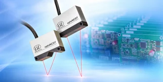
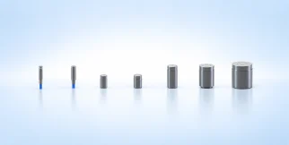
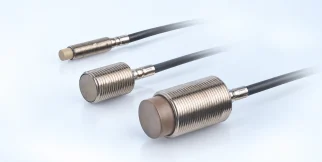
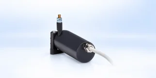
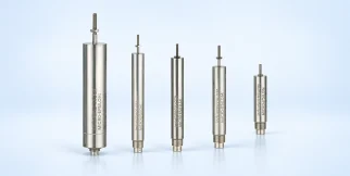
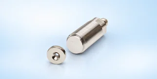
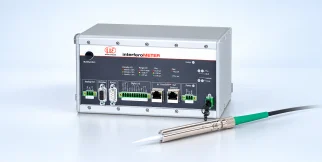
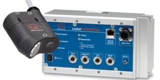
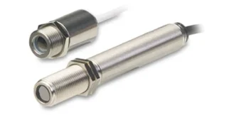
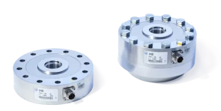
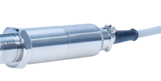
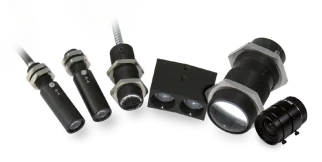









induSENSOR clamping stroke sensor Inductive (eddy current)
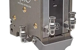
induSENSOR clamping stroke sensor: sensors and measurement devices by Micro-Epsilon for inductive (eddy current).
Download the datasheet (opens in a new tab) This series on the Micro-Epsilon site (opens in a new tab)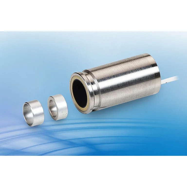
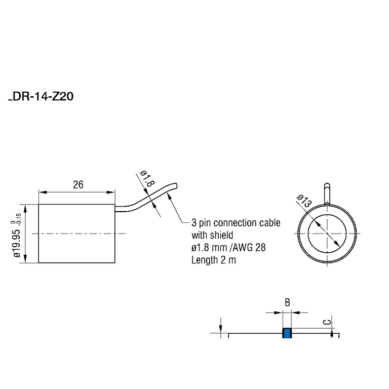
Shared technical specifications for the series
Properties every model in the series has. What differs is in the models table below.
Range across models
The span covered by the models of the series together — not the range of each model.
| Resolution | 12–14 µm |
|---|
Models in the series
One column per model: what differs between the models of the series.
| Parameter | LDR-14-Z20 eli-m-10269c520f130be36b9a370f | LVP-25-Z20 eli-m-645347281e04e5fbc6c632bb |
|---|---|---|
| Operating temperature | -40–120 °C | -40–120 °C |
| Interfaces | ethercat | ethercat |
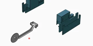
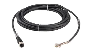
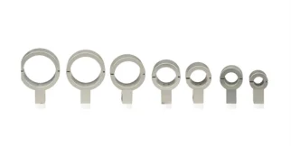
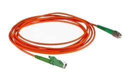
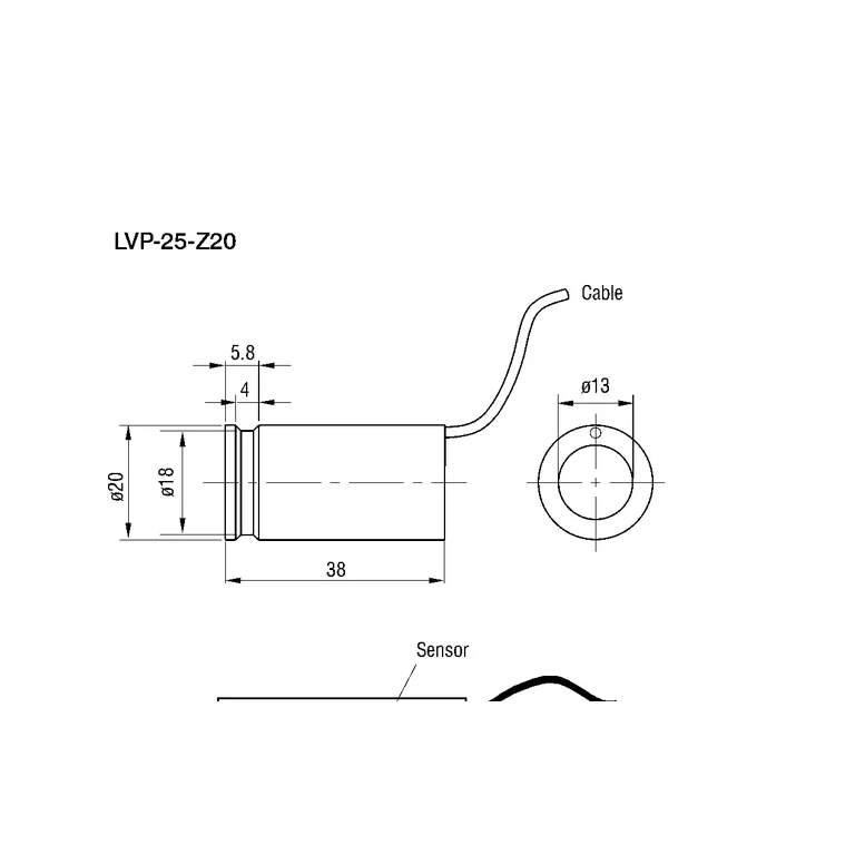
| quantity_specification | 14 mm clamp-stroke sensor; target sleeve fits the documented D8 or D10 drawbar. Sensor cable: 2 m, open ends; operating temperature -40 to +120 °C; IP67. | 25 mm clamp-stroke sensor; target sleeve fits the documented D8 or D10 drawbar. Sensor cable: 2 m, open ends; operating temperature -40 to +120 °C; IP67. |
| Resolution | 14 µm | 12 µm |
| interface_specification | Analog 0-10V | Analog 0-10V |
| source_linearity_basis | Independent linearity typ. ≤ ±1.5 % FSO; factory-linearized system option typ. ≤ ±0.5 % FSO. These are linearity specifications, not accuracy or repeatability. | Independent linearity typ. ≤ ±1.5 % FSO; factory-linearized system option typ. ≤ ±0.5 % FSO. These are linearity specifications, not accuracy or repeatability. |
| Number of measurement channels | 2 | 2 |
| Protection class (DIN EN 60529) | ip67 | ip67 |
| source_sampling_rate_basis | The datasheet gives resolution at 50 Hz and 300 Hz; 300 Hz is retained as a conservative supported setting ceiling, not as a separately guaranteed system throughput. | The datasheet gives resolution at 50 Hz and 300 Hz; 300 Hz is retained as a conservative supported setting ceiling, not as a separately guaranteed system throughput. |
| source_repeatability_basis | Manufacturer describes measurement repeatability as high but does not publish a numeric value. | Manufacturer describes measurement repeatability as high but does not publish a numeric value. |
| ADC sampling rate | 300 samples/s | 300 samples/s |
| Status | Active | Active |
| Datasheet | PDF — LDR-14-Z20 (opens in a new tab) | PDF — LVP-25-Z20 (opens in a new tab) |
The industries we serve
-
-
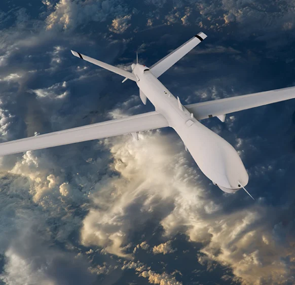
Aerospace
- Aircraft door-lock position detection
- Airlines & Aerospace Our balancing machines and moment weighing scales for aerospace drives ensure maximum precision, ease of use, and modular flexibility delivering reliability and performance without compromise contributing to your economic success.
- Automatic balancing machines Automatic balancing machines from Schenck are advanced solutions for precise balancing of rotating components in automated production processes. We offer systems and stations for balancing crankshafts, wheels and tires, turbochargers, electric armatures, drives, axle drive units, torque converters, drive shafts, disc-shaped rotors, as well as fans. Our systems increase productivity, ensure consistent quality, and are tailored to the needs of the automotive, energy, and industrial sectors.
-
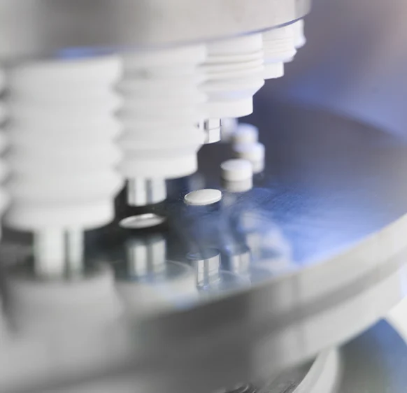
Medical industry
-
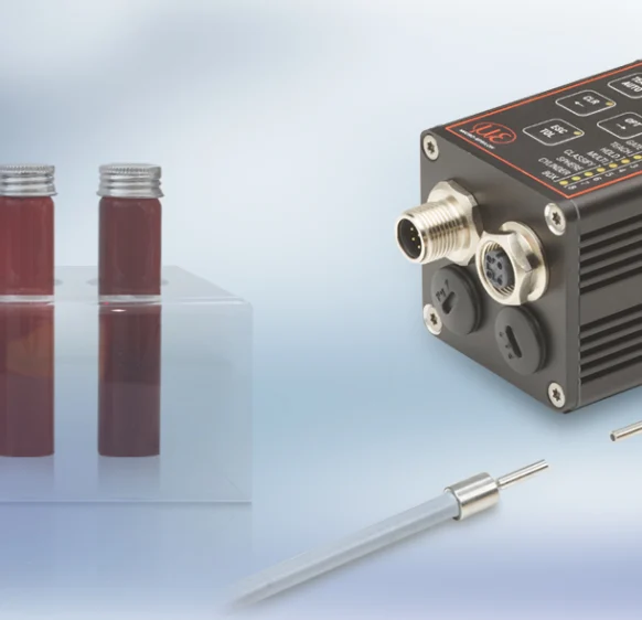
Environment
-
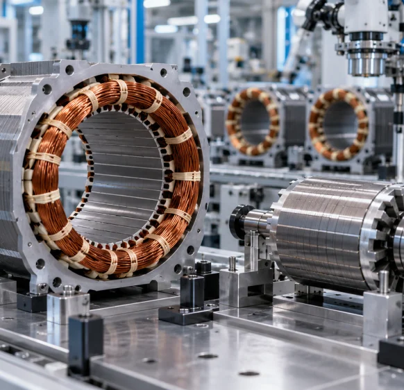
Electric motor manufacturing
-
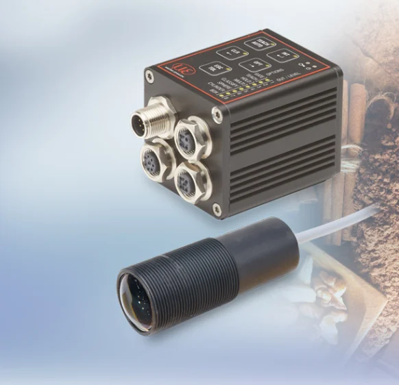
Food industry
-
Automotive industry
- Airlines & Aerospace Our balancing machines and moment weighing scales for aerospace drives ensure maximum precision, ease of use, and modular flexibility delivering reliability and performance without compromise contributing to your economic success.
- Automatic balancing machines Automatic balancing machines from Schenck are advanced solutions for precise balancing of rotating components in automated production processes. We offer systems and stations for balancing crankshafts, wheels and tires, turbochargers, electric armatures, drives, axle drive units, torque converters, drive shafts, disc-shaped rotors, as well as fans. Our systems increase productivity, ensure consistent quality, and are tailored to the needs of the automotive, energy, and industrial sectors.
- Axle Drives With our balancing machines for front and rear axle transmissions, the measured unbalance is corrected by drilling into the drive flanges of the transmissions (welding optional). We support you with our interdisciplinary expertise in the production of front and rear axle transmissions from the initial idea to the design stage through to series production.
-
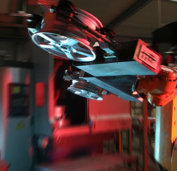
Industrial automation
-
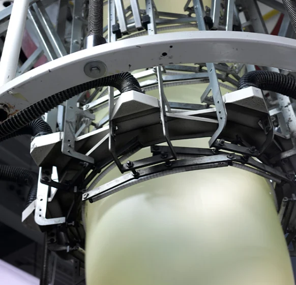
Plastics
-
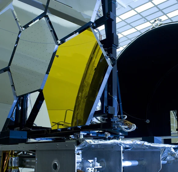
Optics
-
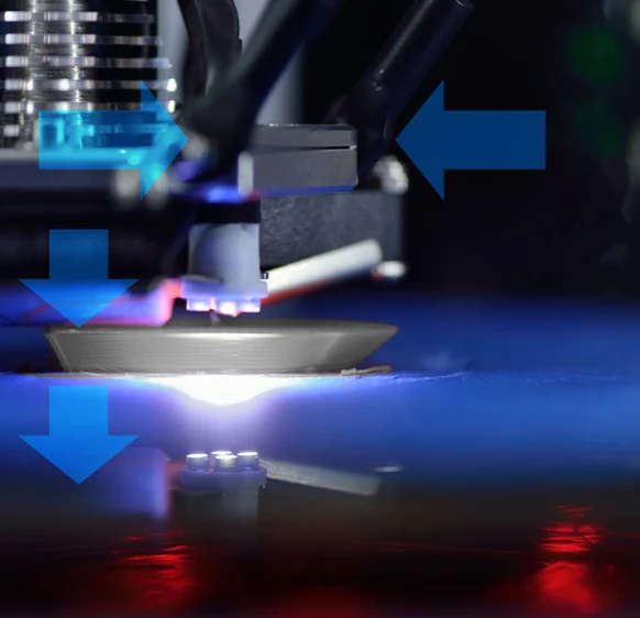
3D printing
-
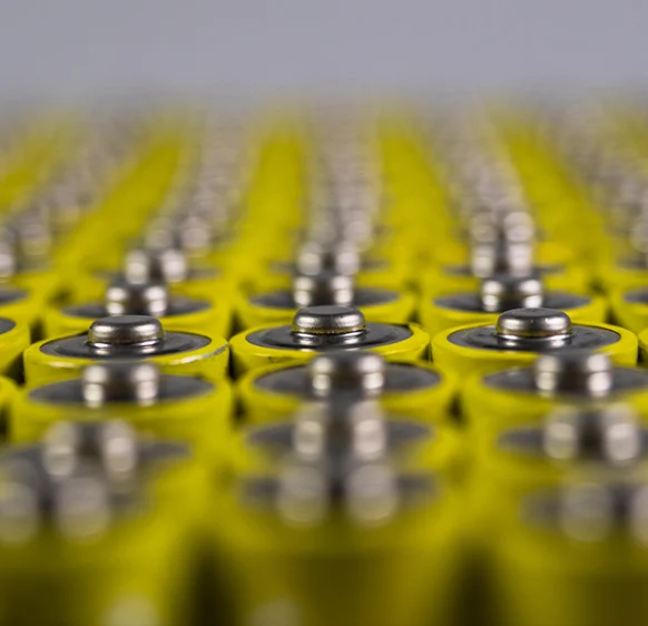
Battery manufacturing
Frequently asked questions
Answers to the most common questions about our products and services
Drawbar travel in a tool-clamping mechanism. Continuous measurement supports distinguishing clamping/release states according to machine mechanics.
It measures a target ring installed on the drawbar. Select ring and drawbar geometry according to the documented configuration and drawing.
No. LVP-25-Z20 specifies 25 mm; LDR-14-Z20 specifies 14 mm. Excitation and resolution also differ.
It is a typical value requiring a linearized controller and appropriate installation. The table distinguishes it from typical ±1.5% FSO linearity.
No. The table specifies separate resolution values at these bandwidths with a compatible Micro-Epsilon controller.
Get a quote or advice
Tell us what you need and an engineer will come back to you.
Request a quote for this product