
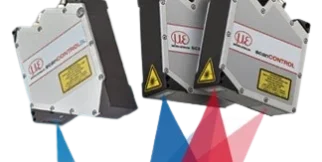
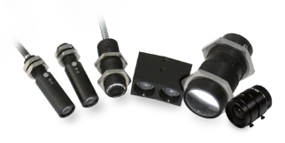















optoNCDT 2310 Laser triangulation
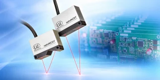
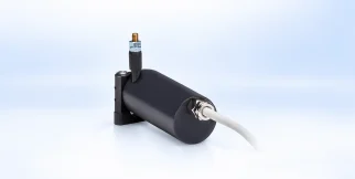
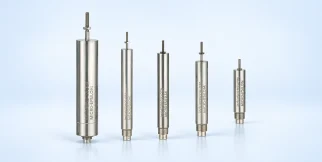
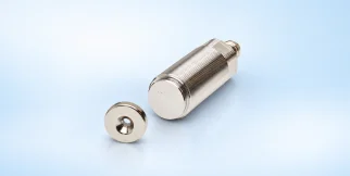
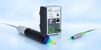
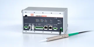
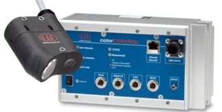
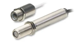
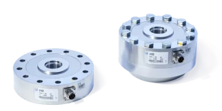
optoNCDT 2310: sensors and measurement devices by Micro-Epsilon for laser triangulation.
Download the datasheet (opens in a new tab) This series on the Micro-Epsilon site (opens in a new tab)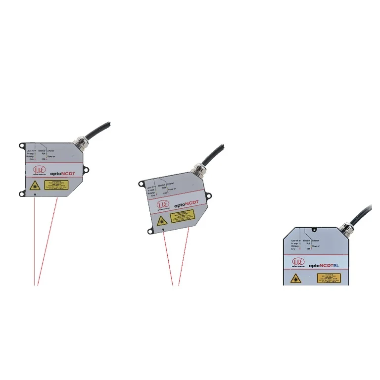
Shared technical specifications for the series
Properties every model in the series has. What differs is in the models table below.
Range across models
The span covered by the models of the series together — not the range of each model.
| Measuring range | 10–25 mm |
|---|---|
| Linearity (% FSO) | 0.03–0.1 % |
| Resolution | 0.5–7.5 µm |
| Measuring window | 90–600 mm |
| Linearity | 3–50 µm |
| Accuracy (% FSO) | 0.03–0.1 % |
| Working distance | 90–600 mm |
| Accuracy | 3–50 µm |
| Light spot diameter | 0.06–0.23 mm |
Models in the series
One column per model: what differs between the models of the series.
| Parameter | ILD2310-10 eli-m-c10808f3052b80cc1fcf391a | ILD2310-20 eli-m-c21f2fd02e4a24dbf65b90b8 | ILD2310-40 eli-m-c094afdcdf168b43e7b11d75 | ILD2310-50 eli-m-fbeb2cdec12186c91add27e7 |
|---|---|---|---|---|
| interface_specification | 4-20mA | RS422 / RS485 | RS422 / RS485 | Analog 0-10V |
| source_repeatability_basis | Official repeatability 0.5 µm under datasheet reference conditions. | Official repeatability 0.5 µm under datasheet reference conditions. | Official repeatability 0.5 µm under datasheet reference conditions. | Official repeatability 0.5 µm under datasheet reference conditions. |
| Minimum cable bend radius | 30 mm | 30 mm | 30 mm | 30 mm |
| source_linearity_basis | Official maximum linearity deviation ±3 µm, equivalent to ±0.03% FSO. | Official maximum linearity deviation ±6 µm, equivalent to ±0.03% FSO. | Official maximum linearity deviation ±12 µm, equivalent to ±0.03% FSO. | Official maximum linearity deviation ±50 µm, equivalent to ±0.1% FSO. |
| Light spot width Y | 0.5 mm | Not specified | Not specified | Not specified |
| Measuring rate | 49140 Hz | 49140 Hz | 49140 Hz | 49140 Hz |
| Measuring range | 10 mm | 20 mm | 20 mm | 25 mm |
| Linearity (% FSO) | 0.03 % | 0.03 % | 0.03 % | 0.1 % |
| source_measurement_reference_surface | The specified data apply to white, diffuse reflecting surfaces (Micro-Epsilon reference ceramic for ILD sensors) | The specified data apply to white, diffuse reflecting surfaces (Micro-Epsilon reference ceramic for ILD sensors) | The specified data apply to white, diffuse reflecting surfaces (Micro-Epsilon reference ceramic for ILD sensors) | The specified data apply to white, diffuse reflecting surfaces (Micro-Epsilon reference ceramic for ILD sensors) |
| Protection class (DIN EN 60529) | ip65 | ip65 | ip65 | ip65 |
| Interfaces | ethernet | profinet | ethercat | profinet |
| quantity_specification | Measuring range 10 mm; start/midpoint/end 95/100/105 mm. At 49.14 kHz the usable interval is 5 mm (100-105 mm absolute distance). | Measuring range 20 mm; start/midpoint/end 90/100/110 mm. At 49.14 kHz the usable interval is 10 mm (100-110 mm absolute distance). | Measuring range 40 mm; start/midpoint/end 175/195/215 mm. At 49.14 kHz the usable interval is 20 mm (195-215 mm absolute distance). | Measuring range 50 mm; start/midpoint/end 550/575/600 mm. At 49.14 kHz the usable interval is 25 mm (575-600 mm absolute distance). |
| Operating temperature | 0–50 °C | 0–50 °C | 0–50 °C | 0–50 °C |
| Repeatability | 0.5 µm | 0.5 µm | 0.5 µm | 0.5 µm |
| source_sampling_rate_basis | Up to 49.14 kHz; the maximum-rate optical interval is 5 mm rather than the full 10 mm range. | Up to 49.14 kHz; the maximum-rate optical interval is 10 mm rather than the full 20 mm range. | Up to 49.14 kHz; the maximum-rate optical interval is 20 mm rather than the full 40 mm range. | Up to 49.14 kHz; the maximum-rate optical interval is 25 mm rather than the full 50 mm range. |
| Resolution | 0.5 µm | 1 µm | 2 µm | 7.5 µm |
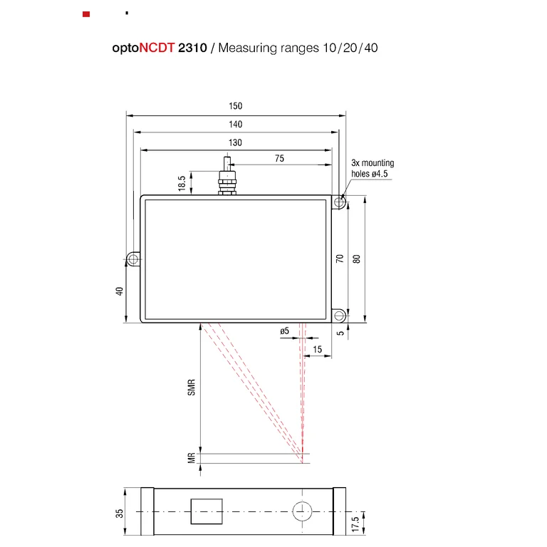
| Measuring window | 100–105 mm | 90–110 mm | 175–215 mm | 550–600 mm |
| source_aluminum_housing | Aluminum housing | Aluminum housing | Aluminum housing | Aluminum housing |
| Linearity | 3 µm | 6 µm | 12 µm | 50 µm |
| Accuracy (% FSO) | 0.03 % | 0.03 % | 0.03 % | 0.1 % |
| Light spot width X | 0.4 mm | Not specified | Not specified | Not specified |
| Cable length | 0.25 m | 0.25 m | 0.25 m | 0.25 m |
| Working distance | 95–105 mm | 90–110 mm | 175–215 mm | 550–600 mm |
| source_connection_plug | 14-pin ODU plug | 14-pin ODU plug | 14-pin ODU plug | 14-pin ODU plug |
| Contact | Non-contact | Non-contact | Non-contact | Non-contact |
| Accuracy | 3 µm | 6 µm | 12 µm | 50 µm |
| ADC sampling rate | 49140 samples/s | 49140 samples/s | 49140 samples/s | 49140 samples/s |
| Light spot diameter | Not specified | 0.06 mm | 0.23 mm | Not specified |
| source_protective_housing_matrix_status | Not specified | Not specified | Not specified | ILD2310-50 is absent from the listed 2310 rows |
| Status | Active | Active | Active | Active |
| Datasheet | PDF — ILD2310-10 (opens in a new tab) | PDF — ILD2310-20 (opens in a new tab) | PDF — ILD2310-40 (opens in a new tab) | PDF — ILD2310-50 (opens in a new tab) |
The industries we serve
-
-
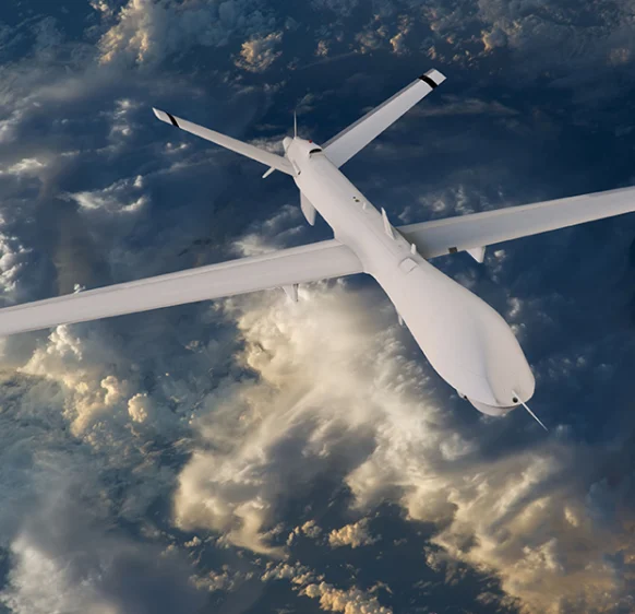
Aerospace
- Aircraft door-lock position detection
- Airlines & Aerospace Our balancing machines and moment weighing scales for aerospace drives ensure maximum precision, ease of use, and modular flexibility delivering reliability and performance without compromise contributing to your economic success.
- Automatic balancing machines Automatic balancing machines from Schenck are advanced solutions for precise balancing of rotating components in automated production processes. We offer systems and stations for balancing crankshafts, wheels and tires, turbochargers, electric armatures, drives, axle drive units, torque converters, drive shafts, disc-shaped rotors, as well as fans. Our systems increase productivity, ensure consistent quality, and are tailored to the needs of the automotive, energy, and industrial sectors.
-
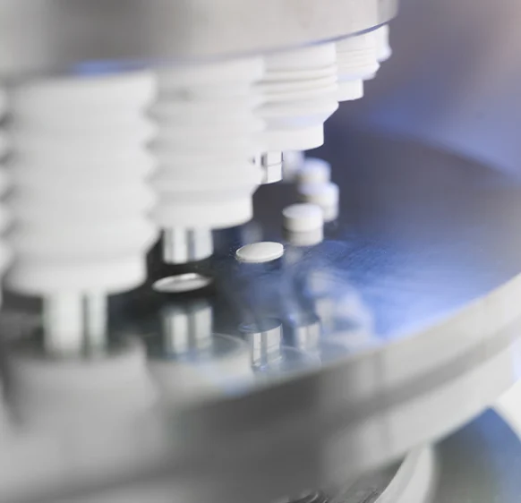
Medical industry
-
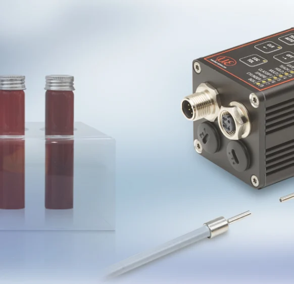
Environment
-
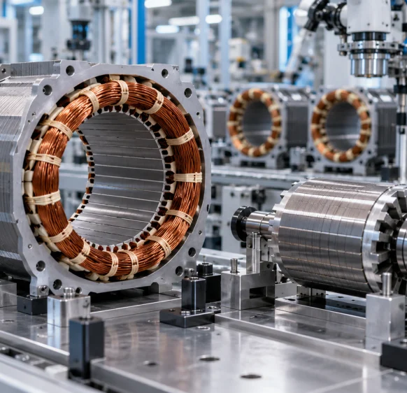
Electric motor manufacturing
-
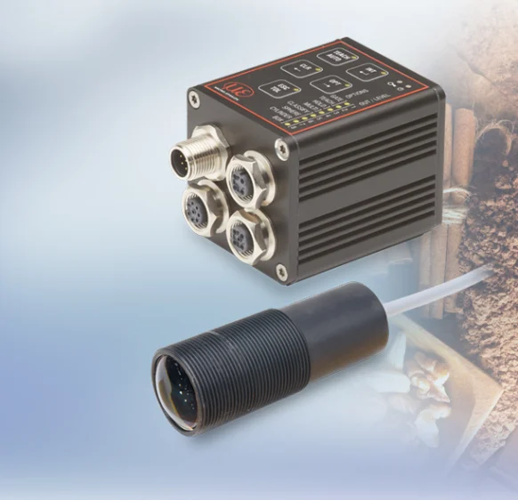
Food industry
-
Automotive industry
- Airlines & Aerospace Our balancing machines and moment weighing scales for aerospace drives ensure maximum precision, ease of use, and modular flexibility delivering reliability and performance without compromise contributing to your economic success.
- Automatic balancing machines Automatic balancing machines from Schenck are advanced solutions for precise balancing of rotating components in automated production processes. We offer systems and stations for balancing crankshafts, wheels and tires, turbochargers, electric armatures, drives, axle drive units, torque converters, drive shafts, disc-shaped rotors, as well as fans. Our systems increase productivity, ensure consistent quality, and are tailored to the needs of the automotive, energy, and industrial sectors.
- Axle Drives With our balancing machines for front and rear axle transmissions, the measured unbalance is corrected by drilling into the drive flanges of the transmissions (welding optional). We support you with our interdisciplinary expertise in the production of front and rear axle transmissions from the initial idea to the design stage through to series production.
-
Industrial automation
-
Plastics
-
Optics
-
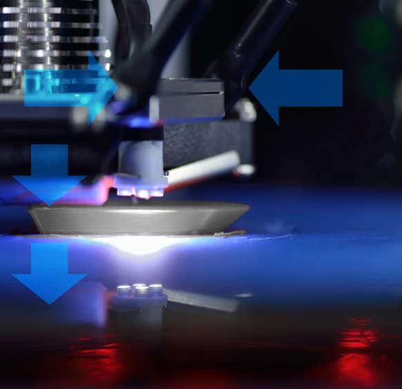
3D printing
-
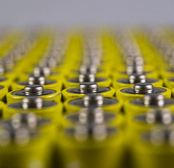
Battery manufacturing
Frequently asked questions
Answers to the most common questions about our products and services
It provides comparatively short measuring spans at larger stand-off distances. Match net span and start distance separately.
No. Bracketed model values specify a reduced window at this rate. The 10 mm model, for example, uses a 5 mm window at maximum rate.
No. The table separates Resolution from linearity and specifies resolution at 10 kHz without averaging. Match each requirement to the corresponding metric.
The table lists 550–600 mm, a 50 mm net span. At 49.14 kHz, the listed window is 575–600 mm.
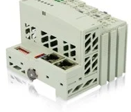
Its measurement electronics are integrated. It still needs suitable wiring and an adapter when the requested output is not onboard the configuration.
Get a quote or advice
Tell us what you need and an engineer will come back to you.
Request a quote for this product